M-19 Cabin
Cabin Construction
revised October 12, 2000
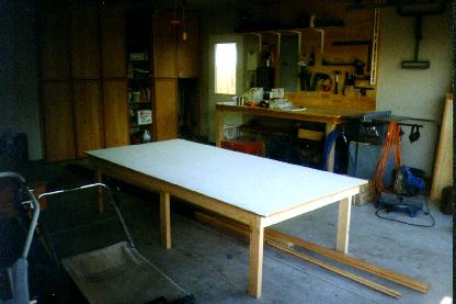
This is my building table. For space reasons, I decided to start with a 4'x8' table for building the cabin. I
will add another 4'x4' to the end when I get to the wings and empennage. I tried to build the table to what
would be comfortable working height, but ended up building what is cheapest and wasted the least
material. The top is two sheets of 3/8" roof decking (which I got for free because they were on the ends of
stacks and weren't perfect), glued and stapled together. Very stout. Paint is leftover flat white from an old
can I found in my garage from when our house was built.
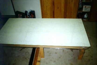
Closeup of my outline layout (not very clear). Clear plastic sheeting is over the top. A roll is only $2.50,
and you only use a small amount of the roll to cover the table. The rest you can use for keeping stuff dust-
free while you sand and build.
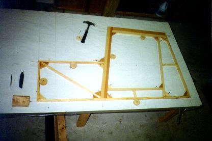
Port side in the jig and nearly ready to glue. I used some wood 'cams' to lock the parts in, and should have
used even more but was too lazy to make them. Nails work OK except you have to pull some of them to
get your part out of the jig and you can't increase the pressure on the piece you jig in place. With the wood
cams, you can go back and 'tweak' them tighter as needed, or loosen them up to remove your piece.
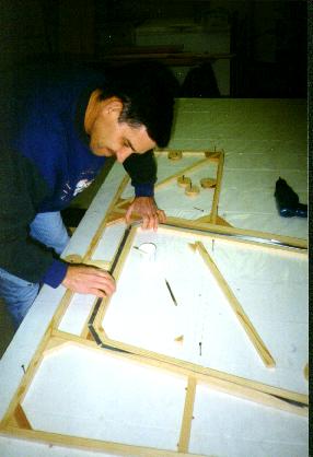
Fitting up my door. Three layers of duct tape inside the door opening should provide adequate gap, plus
keep the door from getting glued into the opening when I glued it up. Epoxy won't stick to duct tape.
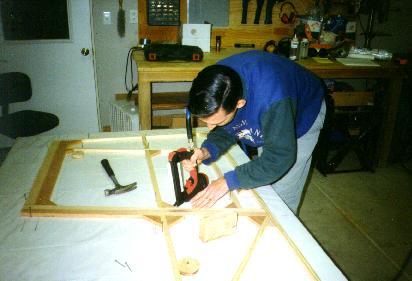
Fitting up the starboard side. This time, I am using the power stapler with 1-1/2" staples to hold the joints
tight for gluing. Boy does it work great, but you have to be careful with fir because it splits easier than
spruce. If you get too close to the edge with a staple or don't fire it in perfectly straight, you'll crack the
wood.
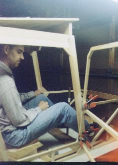
And here's the fearless Squirrel pilot, preparing to secure the door of the cabin and depart for a morning
sortie. I figure this is about where the actual seating will end up, fore and aft. Seat bottom will be about 3"
higher than this, but not too close... note where eye level is relative to top of door. Imagine line of seat
harness, almost straight back from the shoulders- and there's no structure there to anchor to. I plan to add
some anchor points to the sides, or an extra crossmember at that level. Also note distance from heels
(rudder pivot point) to firewall; this should be no less than 8" according to design books. Perfect, Marvin!
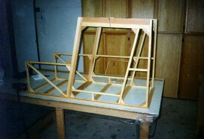
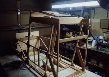
Here are the two sides with the floor crossmembers roughed in. Note several things. First, I have stapled
down carefully-measured strips of leftover (knotty) wood to form the outline of the cab. I squared these up
as accurately as I could, then stapled them down. Insert the two sides, cut and fit the x-members, and
everything will stay square if you keep the cabin sides plumb. A spirit level takes care of this. Note also
that I went ahead and framed the lower part of the starboard side the same as the port (door) side, even
though the plans don't call for it. I felt better doing this than just having the single 3/4" member along the
bottom edge on that side. Not only that, but it gives me a place to mount small blocks for the rudder cable
fairleads which I plan to use instead of guide tubes to route the cables along the cabin sides. My gussets
are all somewhat uniform in size, although the plans don't call for any specific size for these. Only ones
called out are the two 3" ones at the forward top of the cabin, where the sides meet the firewall (not
installed in this photo). I made almost all of my gussets from 2-1/4" material, since I had several pieces
that width. Some I had to trim smaller because my angles didn't cut right the first time. OK, so it actually
happened quite a few times! %^)
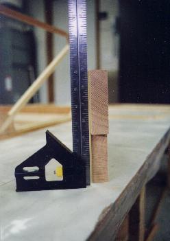
This is an end view of my main cabin through-spar, showing the grain. Vertical grain, as defined by grading guidelines, since the majority of the grain is less than 45 degrees. This particular piece has very tight grain and is very dense and heavy. It was located in a lumber yard's cutoff bin as a 2x8 about 4 ft. long, dirty with pigeon poop. Cleaning up, planing to dimension, and cutting to shape put it right!
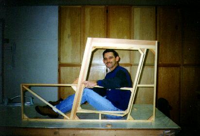
Study this one carefully, if you're concerned about the space in the cabin of the Flying Squirrel. Since this photo was taken I have lowered the seat another 1", all the way to the cabin floor, and now can lean my head back to look out the skylight panel in the roof without touching the top of my head on the cabin roof. I'm 5'-10". The cabin itself is 24" wide, exactly the same as a Super Cub. The stick position shown is as per plans, but I will be curving mine back, since my hands in the photo are right where I want the stick and throttle. Note that I moved my door to the starboard side instead of port as called for in the plans. The seat shown is just a mockup.
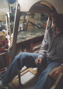
Here's another shot showing the available headroom and pilot's position in the cabin. Seat, stick, and rudder pedals are mock-ups for purposes of establishing relative positions. My rudder pedals are moved outboard so I can use pulley and fairlead to route the cables through the cabin rather than guide tubes.
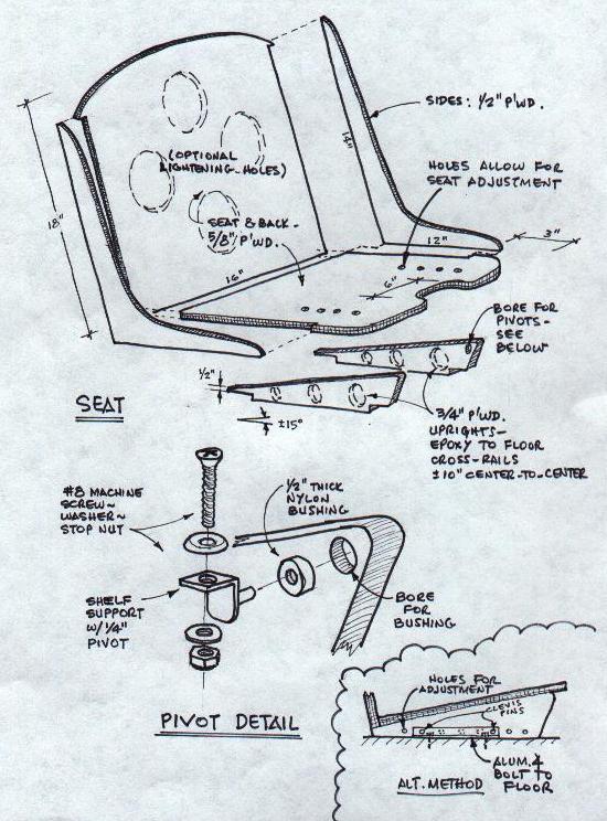
Here's a sketch of the seat construction I'm using.
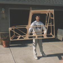
Here's my best bud Mark Dew (he's the guy with all the great tools and workshop that I borrow all the time!) holding the 16 lbs. cabin structure of the Flying Squirrel. Try this at home!
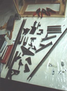 Here's a shot of some of my 4130 fittings, fresh from the fabricator (I'm not set up to work steel). Surprising how small some of them are, compared to the image I had in my mind; many of the drawings in the manual are full-size. These are stout, sturdy fittings!
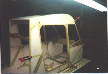
 Here is a shot of my cabin structure again, showing some of the additional framing which I've installed. The crossmember at the back is where I'll mount my shoulder straps. It is attached to the uprights with epoxy and #8 screws. The two lower 2-1/4" diagonals are for the future floatplane setup, using an additional steel channel under the rear corner of the cabin. Probably overkill, but the 3/4" stock looked too skinny for when I drop it onto the water too hard ;o) The two small verticals in the side of the cabin below the window opening are for mounting an armrest so I can have something to rest my arm on for operating the engine control quadrant. The seat uprights are visible here (3/4" plywood); should have made lightening holes. Last item somewhat visible here is the framing I added in the roof, for the skylight. Don't want to miss that bogie moving in on me from overhead, eh? ;o)
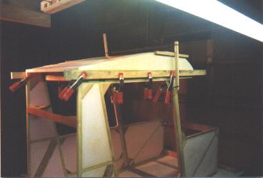 Here are my wing chord plates being glued in place. Besides the recommended board clamped on to hold it, I stretched a bungee across the top with some additional boards to get good gluing pressure at the main through-spar.
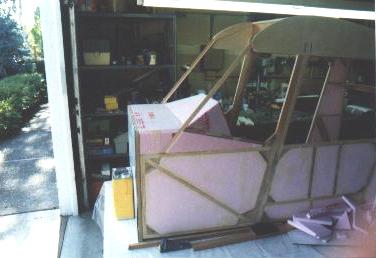
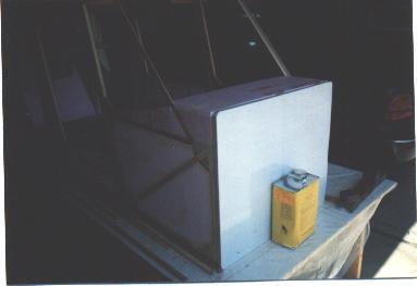 This is my firewall (protective film still on the aluminum), temporarily in place so I could cut and fit the top deck pieces. Windshield framing temporarily in place too. The bottom edge of the firewall hangs below the bottom edge of the cabin frame by 3/4"; I just propped my cabin up on some 3/4" wood strips to get the proper relationship.
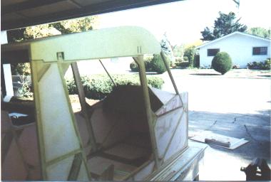
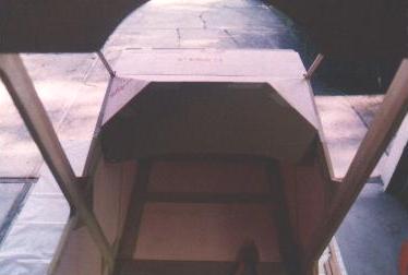
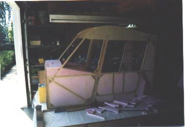 Okay, here is the way the top deck looks from the side, including my modification of the side window framing (I sloped it down aft, rather than running it horizontal).
 Here's somewhat the same view, but with my instrument panel cardboard cutout in place, showing the way I'm shaping the interior deck.
 Here is a view into the cockpit with a cardboard cutout of the "stock" instrument panel taped in place.
 Same view, but with my modified instrument cardboard cutout in place. I checked the view out the front with the higher top edge, and it doesn't seem to obstruct the view much. (Another photo shows the view out the front).
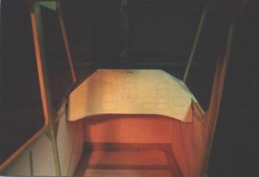
 Here's the modified instrument panel, looking down through the skylight.
 Another shot of the inst. panel, with a CAD plot of the instruments glued on. Probably not real clear in this shot.
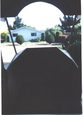 This shot simulates the view out the front, on short final to my neighbor's yard ;o) I don't think the higher panel will cause me any problems seeing out the front; all I could see with the stock instrument panel was just more of the top front deck.
Advance to Cabin Construction II
Return to Oscar Zuniga's M-19 Homepage