Cabin Construction II
M-19 CABIN CONSTRUCTION II
Updated October 20, 2000
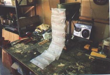
My friends and co-workers are always curious about my project, and they are also always helping me scrounge things that I need for it. So one day I walk into my office and I see this on my chair. You know what this is, right? It's the blister pack stuff you get when you receive some delicate computer stuff, instead of styrofoam peanuts. So there's a note attached, which says: "Seat cushion may be used as a flotation device in the event of a water landing". This is the type of friends I have.
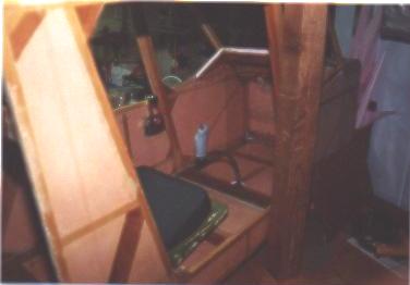
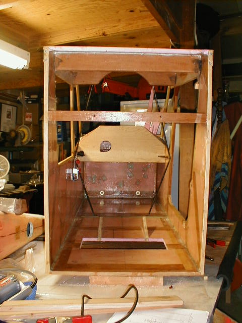
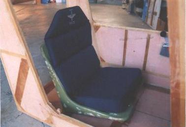 Here is the Nelson padded seat that I'm trying out for fit in my home-made seat. The Nelson unit is very nice; it's cordura with foam inserts, and the seat and back are available in various thicknesses. This is the 2" seat bottom with 1-1/2" back. Needless to say, I've since had to lower my seat mounts to get down where my head will clear the cabin roof. BTW- in this shot you get a good view of the extra 2-1/4" members I installed from the aft corners of the cabin up at an angle, to transfer loads up to the frame from the rear mounting point for floats. That mount will go right under the aftmost cabin floor cross-beam, where the empennage joins the cabin. Also visible are the verticals which I installed inside the cabin to mount an armrest on, placing my hand right at the throttle. Faintly visible are marks where the armrest will go.
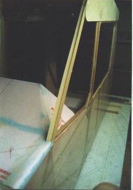
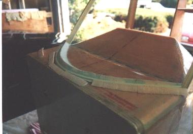
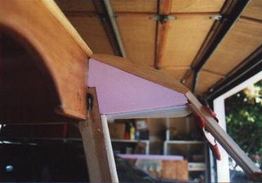 Here is how I did my 'horns' where the wing chord plate sticks forward of the main through-spar. I deleted the section of roof over this area, wrapping my windshield back to the main through-spar to provide more forward/upward visibility. There is a piece of 1/4-round molding at the top edge of the through-spar to attach the aft edge of the windshield to. The top edge of the 'horn' is a piece of scrap wood shaped to follow the curve of the chord plate but 1/8" smaller to allow the polycarbonate windshield to end up flush with the outer edge. Then the rest of the horn is filled in with foam and glassed over (not yet glassed in this photo), to add stiffness to the horn now that it doesn't have roof to stiffen it. Bottom edge of the 'horn', the white part, is a piece of plastic molding used to join two sheets of wall paneling, but I'm using it to hold the top edge of my side window.
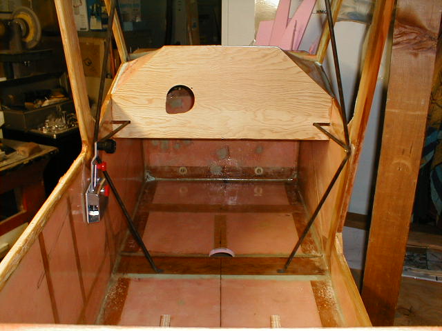
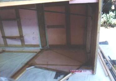 This is a shot of the inside of the cabin, just showing one of the cabin brace struts being fitted, as well as the two angle wedges used to support the top deck. Also maybe visible is the area where a cutout will be made for the control stick universal. The strip of 1/4" ply at the center of the floor was glassed in to provide something to fasten my metal floor scuff plates to.
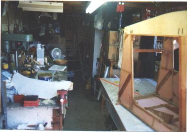 Hmmm... don't know how visible this is, but this is a shot looking into my shop. Cabin structure on the building table on the right, and shop table (very messy!) on the left. I've stretched some twine back from the aft edge of the cabin to where the tailpost will be, to see if there is any way I can build the whole structure in this space. It will be tight...
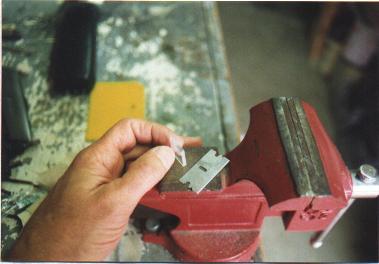 Here is what 1/8" polycarbonate looks like. The stuff is thick! My side windows are 1/16", but the front windshield is 1/8" thick because the lighter stuff was too flexy for the way I have mine extended.
 Tricky stuff, eh? Notice that the sloped member which carries the edge of the windshield is cut at a variable angle from top to bottom. Since the windshield is curved at the bottom but flat at the top, I decided to try cutting a twist into the framing member. Mark, my building partner, fed the wood through the saw at a steady speed while I cranked the blade angle adjustment. We practiced on about 6 scraps before we got it right, but it turned out pretty nice.
 Do you see where this is going? The manual calls for the bottom edge of the windshield to "die" into the top deck and get a fat bead of sealant, but I decided to make it more secure. I've cut small wedges of wood to provide mounting points for screws, then infilled with wedges of foam. The whole thing will get glassed in. Temporary nails along edge of firewall are where I will have small alum. angle clips and Southco 1/4-turn fasteners for the cowling. Top and bottom will be Southco'd for quick and easy removal.
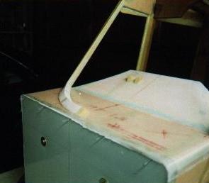
 This is how the windshield lower edge/top deck developed. I know it looks heavy, but it's really only foam wedges and filler, and I had to glass over the top deck anyway, so the weight was negligible. The white piece is some plastic stuff you get at the hardware store for joining wall paneling; I just doctored it a little to fit where I wanted it to, and it will receive the lower edge of the windshield. This all got sanded smooth and glassed over. Better than the fat bead of windshield sealant, IMHO.
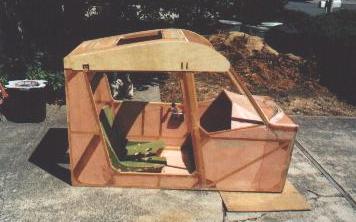 Here's the cabin at the end of Section III of the manual... sort of. No metal fittings on it. The seat is temporarily in place, but I've since re-done it to lower it about 2". The throttle quadrant is temporarily in place as well. What you see here weighed about 60 lbs., and represents about 200 hrs. of building time. I know that seems like a lot, but there are other sub-assemblies that are not in this picture that took lots of time, and won't be evident for quite a while yet. The door and latch took a while, for example, but aren't in this picture.
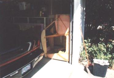 This is what I did with the cabin the winter of '99 so I could free up my building table to do the empennage. Neat, huh? But it sure looks small and lonely there in the corner of the garage. I later pulled it back out to test-join the empennage to it and turn it into a real airplane fuselage! For real!
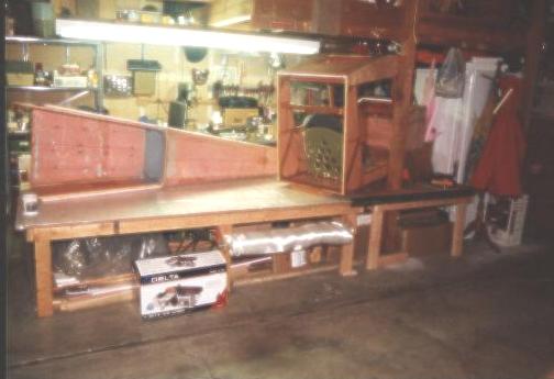 Here is what my expanded workspace looks like. I added 4'x4' to the previous 8'x4', giving me a-l-m-o-s-t enough to build my wings on. The problem is that there is a support post running through one side of the table ;o( But at least I have more space and a bit more organization (!) My engine is under the table at left, covered with plastic. Fiberglass cloth roll is the white stuff right below the center edge of the table.
 Here's what the inside of the cabin is looking like with the stick in place. I cut the hole in the floor, mounted the universal, and mounted the stick. Seat and cushion in place; instrument panel removed. (See that 4x4 post blocking the opening into the cabin?)
 Close-up of the control stick and universal. It turned out nice. I don't know how you could comfortably fly the airplane with the stick coming straight up from the universal; I curved mine back so I can fly with my arm resting on my right thigh rather than holding it out in front of me. Bottom edge of instrument panel on the left.
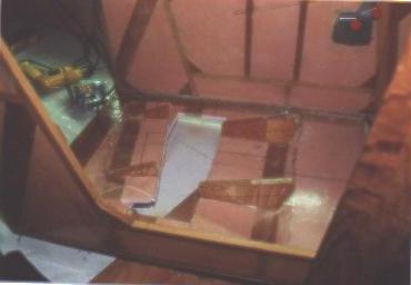 Now this really hurt. What I did was mark and cut out a rectangular hole in the floor of my cabin. The cutout piece is to the left of the hole. The two 3/4" plywood seat supports also got cut down 2". The object of this exercise was to gain headroom in the cabin. Additional floor framing yet to be added to strengthen where I cut out the floor.
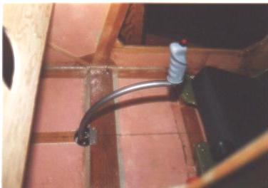
 Don't know if you can see this too well, but with the seat temporarily dropped into place in the new floor cutout, the aft corner of the seat is now "submerged" 2" into the floor. Belly will enclose it. Seat is still hinged at the front, giving me access to elevator control cables running in the belly.
 This is a view into the cabin, showing the hole I cut in the floor to allow lowering the seat 2" to gain more headroom. Also shows the cabin braces (3/8" 4130). Not yet bolted in at the ends, but you can see how stout the structure becomes. Pay no attention to the back side of the firewall there; one of my first attempts at fiberglassing, resulting in about a million air bubbles which had to be sanded out and patched. This has all been filled, sanded, and smoothed so you'd never know I was a beginning fiberglasser. Also visible is my throttle quadrant. I lucked out and the handles clear the cabin brace mounting bolts just about right. Also my preliminary plywood instrument panel, which has since been replaced by the permanent aluminum one. I didn't notch out the bottom edge, just ran it straight across, and there is still plenty of room getting your feet and legs into the cabin.
 Close-up of the instrument panel area. Still didn't have the mounting clips installed on the backside, and the sides and top were later fitted a bit better. I thought I'd be installing a visor over the top edge but will try it without first, to see if the instruments are all visible in bright sunlight. Fuel lines, pitot/static lines, and headset wiring will follow the cabin brace into the slot in the panel, back into the area behind the panel.
Return to My Flying Squirrel Home Page