Steve's Wing
CONSTRUCTION OF STEVE'S WING
Posted September 5, 2002
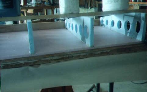
When the ribs are laid out for gluing to the spars, they should be checked for squareness, equal spacing, and even height. Here a board is laid across the tops to check that all the ribs are the same height. All ribs are 3/4" thick extruded polystyrene foam with lightening holes.
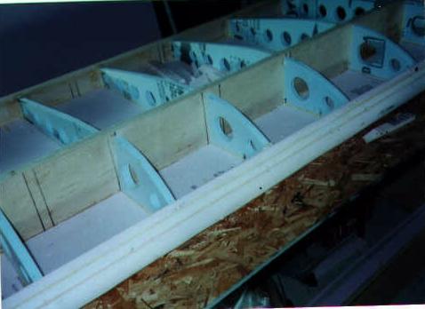 Here the center section ribs and nose ribs are glued in place to the spars and the nose piece is glued onto the nose ribs and shaped. This shaping can be done with a long board or piece of PVC pipe with 80 grit (or rougher) sandpaper glued to it. Such sandpaper is available where you rent floor sanders, or the open-weave mesh used for sanding drywall joints can also be used.
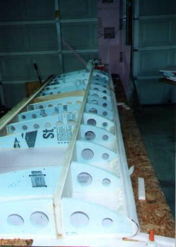 All ribs are in place in this photo.
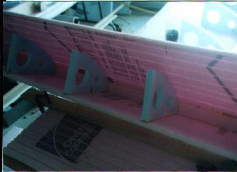
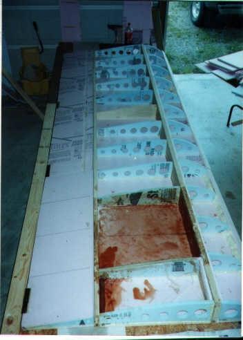 Here's a very informative photo. Note the fuel tank bay, consisting of two rib cells. The size of this bay can be adjusted to obtain the desired fuel capacity (while keeping in mind the weight and balance). A tube is glued in place between the fuel tank bay and the wing root at the aftmost corner of the fuel tank bay, to carry the fuel line from the tank to the cabin. This tube, and the fuel tank bay, must be completely sealed with resin because any fuel leakage or fumes will dissolve the wing foam instantly! Also to be noted in this photo is that Steve has changed one wing rib from foam to wood out where the wing struts attach to the spars. While not called for in the plans, this change does add a nice bit of stiffness at the strut attach point and won't add significant weight. Note also that in this photo the trailing edge ribs have already been covered with foam, forming the aft section of the wing. The center and nose ribs will be similarly closed up once work is complete on the fuel tank bay. One last thing to note is that Steve has changed the rib spacing from the plans; the plans spacing for the nose ribs is 8" on center and for the main and trailing edge ribs it's 12" on center. It looks as if Steve has used 12" o.c. uniformly, which is not an issue with this wing (there are enough nose ribs and a rigid enough assembly that there will be no sagging or buckling of the nose section with the wider nose rib spacing).
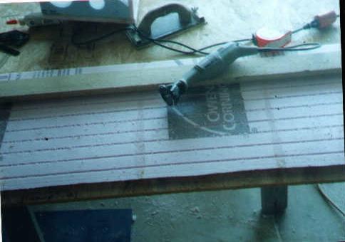 Steve's method of grooving the inside surface of the foam board that will form the curved forward section of the wing, from the nose piece to the main spar. Since this section of the wing is curved tighter than the foam board can bend, grooving is required.
 Test-fitting the curved leading edge section around the nose ribs, as viewed from inside the wing. Quick-set epoxy is used to attach the curved foam section to the ribs once it's all fitted. Straps or tape can be used to hold the curved section while the glue sets.
If you're not building yet,.........................why not?
Return to My Flying Squirrel Home Page