Spar Test
Alternative Spar Load Test
by Marvin R. Barnard (engineering technician)
and Steven Imlay (assistant technician)
December 29, 2001
I've spent the last few weeks experimenting with some
beam loading tests hoping to find a suitable alternative spar (for a
number of reasons).
#1, to reduce cost,....
#2,to reduce weight...
#3 I had the opportunity, as a friend supplied most of the labor and resource. Many thanks to Steven Imlay!
The following test summary is as applied to two spar design variants of the traditional solid or routed plank spar. One is a composite spar using wood, foam, and fiberglass. The other is an all-wood I-beam shape with solid flanges, plywood web, and web stiffeners.
 A composite built-up spar section measuring 3/4"x 7"x 72" was
fabricated using 3/4" x 3/4" wood flange members, with 3/4"x 5-1/2" foam
web insert which is also reinforced with wood 3/4"x 3/4"x 5-1/2" vertical
compression struts installed with progressively closer spacing toward
the anchored end (relative to the increasing mechanical disadvantage of
the load) and wood web-end blocks on each end, 5-1/2"x 12". All foam-to-wood edge joints are filled with mirro fill paste mix, and each side is
resin-clad with 9-oz. 45 degree bias fiberglass cloth, thus becoming a
box beam.
A composite built-up spar section measuring 3/4"x 7"x 72" was
fabricated using 3/4" x 3/4" wood flange members, with 3/4"x 5-1/2" foam
web insert which is also reinforced with wood 3/4"x 3/4"x 5-1/2" vertical
compression struts installed with progressively closer spacing toward
the anchored end (relative to the increasing mechanical disadvantage of
the load) and wood web-end blocks on each end, 5-1/2"x 12". All foam-to-wood edge joints are filled with mirro fill paste mix, and each side is
resin-clad with 9-oz. 45 degree bias fiberglass cloth, thus becoming a
box beam.
For the all-wood I-beam, a 3/16" oak plywood web was used with 1" ash flanges, and a few vertical flange stiffeners.
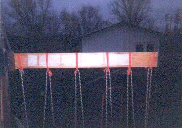
The beam is fixtured into a clamp bracket that is anchored to a post. 6" is occupied by the clamp leaving 5'-6" extended to bear the
load. Nylon strap rings around the beam allow direct vertical loading into a rope of continuous loop through each ring and around a suspended load plank, allowing uniform load distribution. The photo above shows the composite beam in its unloaded state.
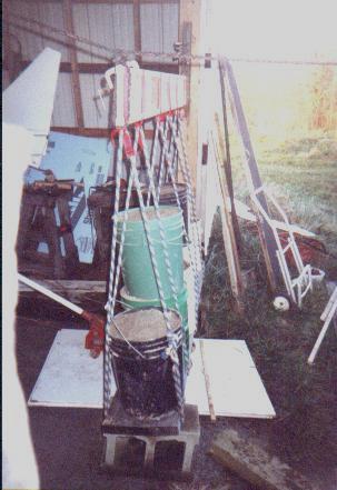 The all-wood I-beam test specimen is here shown in the loading fixture. The weights are applied in traditional manner and measurements taken at intervals. Beam end deflection was estimated, and the applied load weight was weighed to within accuracy of 4 oz. on a calibrated scale.
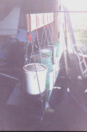 The all-wood beam with more load added. The wood beam creaked and groaned under load, but the composite beam under the same conditions loaded smoothly and quietly.
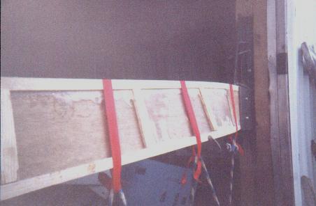 The all-wood beam twisting and deforming under 880 lbs. of load. At this point we unanimously agreed to halt the test because the suspended load was becoming unstable enough to create a risk of giving inaccurate results.
I believe that in a more rigid stable test application and jig to prevent twisting or buckling (as it is held in the actual wing by the ribs and wing skins) the beam would bear considerably more if tested to failure. Mathematical analysis also implies the same. As can be seen in the photo, the tension on the straps (load rings) is most of what is keeping the beam sides from bowing out even more and accelerating failure in torsion. The composite beam under the same conditions and with loading at exactly 880 lbs. had an estimated end deflection of 6" with no detectable delamination, cracking,
torsion, or buckling.
The all-wood beam twisting and deforming under 880 lbs. of load. At this point we unanimously agreed to halt the test because the suspended load was becoming unstable enough to create a risk of giving inaccurate results.
I believe that in a more rigid stable test application and jig to prevent twisting or buckling (as it is held in the actual wing by the ribs and wing skins) the beam would bear considerably more if tested to failure. Mathematical analysis also implies the same. As can be seen in the photo, the tension on the straps (load rings) is most of what is keeping the beam sides from bowing out even more and accelerating failure in torsion. The composite beam under the same conditions and with loading at exactly 880 lbs. had an estimated end deflection of 6" with no detectable delamination, cracking,
torsion, or buckling.
Woohoo! What does that mean to us? The outboard 6 ft. of the 11 ft. M-19 wing bears 1/4 of the load, and is at the greatest mechanical disadvantage. Because the main spar tested can support 880 lbs. and the main spar represents 80% of the wing's total strength, a complete wing can support 1100 lbs. per quarter section. A total of 4400 lbs. can therefore be applied to the airplane (in positive G force) without breaking the wing. In terms of G-force loading for a maximum gross of 850 lbs., this gives (4400/850) = 5.17 G.
Very likely more, but not yet test proven.
So, if you're not building yet.......why not??
Return to Oscar Zuniga's M-19 Project