Steve Eldredge's & Larry Williams' Stearman-type Float Gauges
modified February 11, 2008
modified February 11, 2008
(The following was copied and edited from a narrative that Steve Eldredge had on his website, describing the construction of the float-type sight gauge on his Pietenpol. Also, at the bottom, is Larry Williams' adaptation of Steve's concept.
~Oscar)
Anyone looking in the Aircraft Spruce catalog for the Stearman type sight gauge is out of luck. According to the order-takers they won't have any in stock for TWO YEARS! I couldn't wait that long even though it is nearly a perfect fit and is only about $30. Instead, I built my own for about $5. Mine is based on the tank indicator in the 2nd issue of the "Buckeye Pietenpol Newsletter" [long out of print. -OZ] For those who don't have that issue from about 1985, I will explain.
I built the center-section tank out of .040 aluminum from our local sheet metal shop. I bent up the bottom tray and ProSealed the sides and baffles in. The sight gauge had me stymied for a while until I came up with a solution involving copper pipe fittings and vinyl tubing. Here's the materials list:
6" long section of 1/2" copper tubing (ordinary water pipe)
1- 1/2" copper tube coupling
1- 1/8" NPT hose fitting
1- hardware store washer large enough to allow enlarging the hole to 5/8" dia.
6" long section of fuel resistant clear vinyl hose
1- large cork
1- small lead fishing weight
36" of stiff 1/16" wire (I used welding rod)
- a few rivets
- a few square inches of scrap aluminum
- 1/8" NPT tap, safety wire, silver soldering tools, etc.
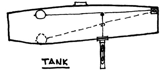
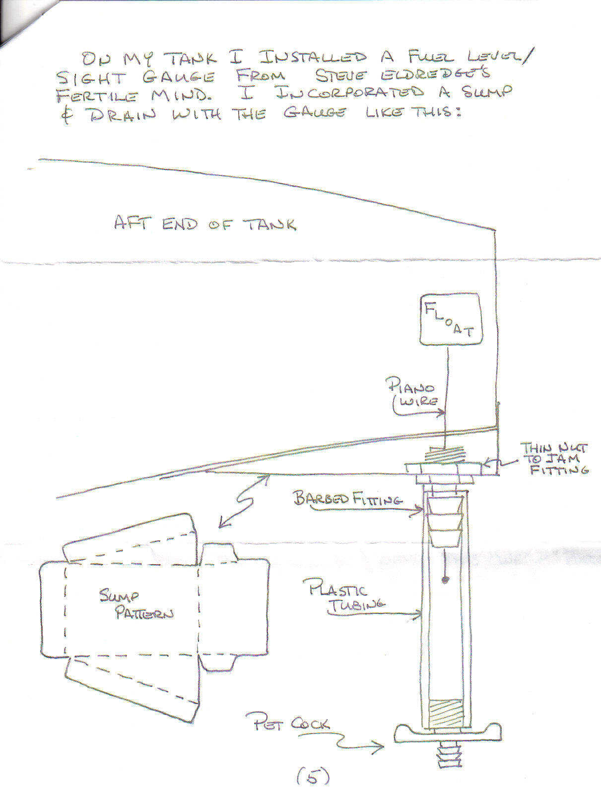
Inside the tank I made a bracket to hold one end of the 1/16" wire near the top of the tank and hinged it there. At the other end, I fastened the float and made the overall length such that the float would be in the deepest part of the tank... 16" or so from the back wall of the tank.
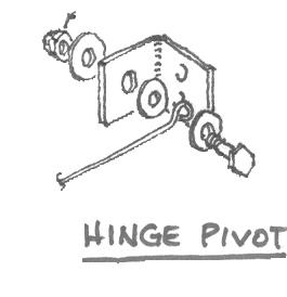
About 8" from the hinge point I bent a 360 degree loop in the wire which would provide an attach point for the float indicator that would poke through the bottom of the tank.
Next I cut a shorter length of 1/16" rod, about 12" long, to serve as the indicator. I bent it to connect to the loop in the float arm and drilled a hole in the bottom of the tank for the indicator rod to pass freely through. The indicator wire is cut to a length such that at full up cork travel the end of the indicator is still protruding at least 3/4" from the bottom of the tank. At this point I had an indicator that would move vertically in accurate proportion to the float position, but I had to make it fuel proof at the hole where the rod protrudes. Here's where the creativity comes in.
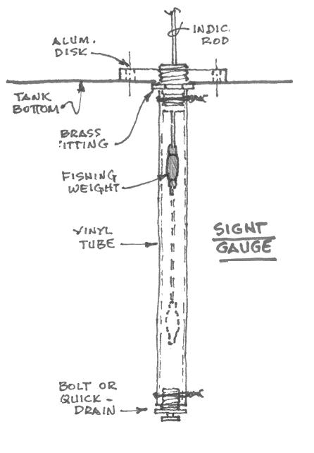
To strengthen the inside of the tank and to have material to anchor the fittings, I made a 2" diameter aluminum disk out of 1/4" thick stock, drilled a hole in the center and tapped it to 1/8" NPT threads. I found a 1/8" NPT brass hose fitting at the auto parts store and screwed it into the aluminum disk through the hole in the tank where the indicator rod passes.
The fishing weight is pinched onto the end of the indicator rod and the clear vinyl tubing is slid up over the weight and rod onto the nipple of the brass fitting, then safety wired to secure it. You can put a short bolt into the open end of the vinyl tube and wrap that with safety wire to seal it, but I used a quick-drain instead and have found it to be useful. At this point you have an accurate indicator and a fuel-tight tank, but the indicator gets stuck in the tubing due to the curve that the vinyl retains from having been on a roll all its life. So the final step in the construction is to encase the vinyl tube in a copper tube to protect it and keep it straight.
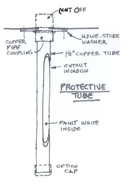
I drilled out a hardware store washer to accept the copper tube coupling, inserted the coupling about half its length, soldered it in place, and then cut the other end off flush with the face of the washer. I then drilled four mounting holes in the washer and up through the bottom of the tank and the aluminum disk. This fitting and the aluminum disk will hold the copper tubing firmly in place on the tank when assembled. I applied ProSeal to the disk, the tank bottom and washer fittings (making sure not to clog the opening or restricting movement of the indicator rod) and bolted the whole assembly together tightly.
Next, I cut the copper tubing to length and cut out a window slightly longer than the travel of the indicator. As mentioned for the vinyl tubing the copper tube can also be capped on the open end or left open if you install a quick-drain on the vinyl tubing as I did. After cleaning all edges and painting the inside of the tubing window with white paint, the tubing is slid up over the vinyl being careful not to bend the indicator. The window cutout is turned to provide the best view of the indicator for the pilot. My sleeve fits very snugly over the vinyl and its safety wire, making a clean and solid sight gauge installation. Works great!