M-19 Cowling
Engine Cowling Construction
September 26, 2009... started over! Updated Oct. 4... building new cowling. Scroll to the bottom for newest info and pictures.
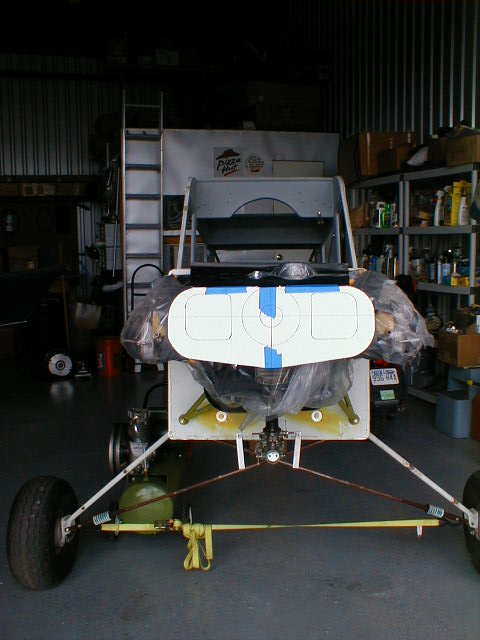
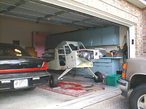 Here's the airframe moved to its new home, our garage in San Antonio, TX. I had hoped to have a workshop or a hangar by now, but no joy... so we keep on working with 1/2 of a 2-car garage. The airplane was moved out of storage on October 4, 2003... exactly 5 years to the day after starting this project. In this photo, I've started fitting the foam pieces to build the engine cowling. The starting point was to get a nose piece the size and shape of the prototype's (about 7"x10") cut out of plywood, bolted to the prop flange, and a corresponding foam nose piece attached. Then the top piece was rough-shaped and fitted, during which I discovered some interference with the engine oil filler/breather cap and one or two other things.
 A little better view of the top piece. Simple, single curve.
 Side view of the pieces as they fit. My engine mount is longer than stock due to the magneto on the rear, but it doesn't look too bad with the slightly longer nose (3" longer than stock). Weight and balance will be calculated and adjusted accordingly.
 Starboard side pieces fitted. The process involves slowly measuring, trimming, and rough-fitting in place, then mixing up some 5-minute epoxy and gluing into place. Hot glue could be used instead. Duct tape around the nose of the fuselage at the firewall will prevent the fiberglass cowling layups from sticking to the fuselage..
Starboard side view, showing the bottom piece fitted. The bottom piece is nearly a straight, flat piece so should be fairly easy to glass (fingers crossed!) The aft line of the bottom of the cowling should fair right into the belly panel of the airplane, which is not installed yet.
This is a head-on view of the cowling, and don't worry if things look out of whack. Remember that all the square edges get sanded to a round shape, and everything should get trued up if my eyes work right. I'm thinking of adding a small opening in the nose piece right below the prop hub, to let some blast air hit the oil pump and ventilate the cowling in general.
My idea is to create a carb air intake like the one on this Super Cub. Whattya think?
 Port side, with panels rough fitted. Note that I've added a piece of foam on top, from which I'll create a 'blister' to clear the oil breather/filler cap. I think I'll include the blister in a hinged access door to allow access to the filler and dipstick.
 And here's the assembly after shooting all the cracks, gaps, and holes with expanding "Great Stuff" urethane foam. It really dries hard! Sanding is next...
 Here's what it looks like after knocking off the hard edges and most of the gooshed-out white foam. The blister on top is pretty well smoothed into its final shape, most of the corners and edges are symmetrical (but not all!), and it's starting to look like something. Keep that Shop-Vac handy for all the sanding dust!
 A head-on shot with the intake manifold and carb installed show a few things. For one, nothing seems to be working out as far as symmetry. Note that the bottom edge of the cowling is not square with the bottom of the firewall, the nose piece is not square, the top edge of the cowling is out of square a little bit, the carb isn't exactly centered on the cowling centerline, and so forth. But this is the beauty of foam: you just sand things till they get squared up or add some more foam to build it back out. In my case, you just shrug and keep going ;o) Actually, I'll be adding a piece to the bottom to take care of the worst of it, but the rest will sand out. Note also where I'll be adding an air intake right under the prop hub.
 Side shot shows where the cowling part line will be (some of it, anyway), and also shows that the carb really hangs out there. But I'll have my oil cooler mounted aft of the carb so the cowling will have to be at least that deep to 'swallow' the oil cooler. And my carb heat air box will have an offset outlet to the carb, allowing me to tuck the box up against the underside of the cowling. You'll see as the work develops in the weeks to come.
 This view shows that the edges are starting to soften up, although I'm not using radii as large as Marvin's because I didn't build the foam up thick enough in the corners and I'll sand through if I round off the corners too much. Anyway, this view also shows the top blister for the oil breather/filler and my idea of where the access door will go for the filler and dipstick. Two camlocs will hold the door in place and a short piece of piano hinge along the back edge of the blister will allow it to swing out.
 Here's the oil cooler mounted on the lower edge of the firewall. The connections are on top, so it hooks up nicely. It's a 10"x4" size cooler (VW aftermarket). Mounted on two 1/4" studs with some aluminum angle stiffeners and all-metal locknuts. This is the last piece needed in place before I can start figuring out what the 'chin' will shape up to be. It's got to enclose the intake, carb heat box, carb, and fair into the oil cooler.
 I fabricated a carb heat plenum out of cardboard to see how things were going to fit. Black part on the front is a cardboard representation of what the air filter will fit like.
 Here's the mockup from the port side. I will relocate the overboard "dump" outlet from the carb heat box to the other side so it won't interfere with the linkage operation. It is the aftmost outlet on the top of the box. The hole on the forward side is the heated air inlet from the exhaust stack muff. And all of this, including the carb, will be inside a 'chin' under the cowling.
Here's what it looks like after finishing the rough-shaping of the underside and "chin". I laid on the drywall mud pretty thick and it's drying in this photo. Once dry, I'll sand it smooth and apply touch-up to any low spots or voids, then sand that, then apply a couple of layers of paste wax in preparation for laying up fiberglass.
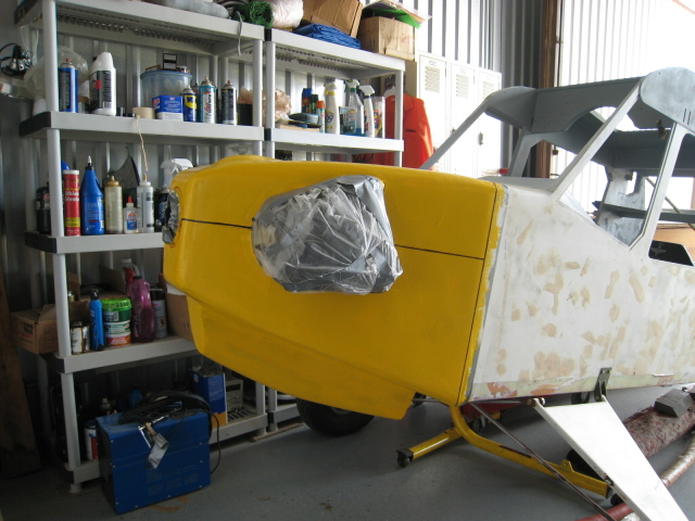
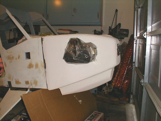
Here's the cowling after a couple of sessions of filling and sanding. Since the layup will go on over this, it isn't essential that the surface be perfect but it helps. Also, resin from the layup will get in cracks and crevices and make it harder to pop the finished cowling from the plug, but any remnants can be removed later using a Dremel or sandpaper. I just got tired of filling and sanding so I proceeded to the next step, which was the application of a couple of coats of enamel. I had yellow on hand so I used it. I marked the part lines with a black magic marker so I could see them through the finished layup later.
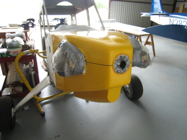
View of the front, showing the part line, cutout for the prop hub, and top blister for the oil filler.
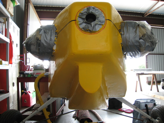
View of the underside chin, air inlet, and the air outlet past the oil cooler. We'll see how well it works once the engine is ready to run. And yes, I know- there are some little imperfections and everything isn't quite symmetrical.

Hard to see what this is because I have laid out my glass cloth and plastic patterns on a sheet of plywood that has a white and grey patterned Formica on it, but basically just showing that I've removed the plastic patterns after fitting them around the cowling plug, then started cutting cloth using the patterns. They will also be used for the layup later. More to follow.
Update Sept. 26, 2009- started over!
 After all of that hard work, I took the box cutter knife and whacked off the plug that I worked so hard to make. Why? Well, because everyone with any VW experience who saw it told me the same thing: that I'd have engine cooling problems with the cylinders buried in the cowling like that, even if I added cooling eyebrows. So off it came!
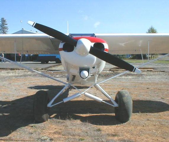
 Here's sort of what I have in mind, or at least my first pass at getting a dimension and proportion that might work. It's the L-19/O-1 "Bird Dog" cowling look. Here are two shots of the "Dawg" that show what it looks like:
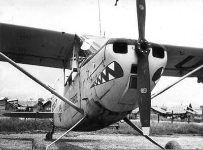
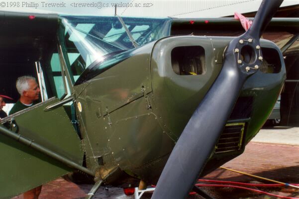
Notice that the cowling doesn't have much taper from the firewall forward to the nosebowl, the air inlets are pretty much simple square holes with rounded corners, the access covers are flat metal with hinges and latches, and air leaves the cowling at its aft edge where I have the oil cooler on my airplane. It just might work.
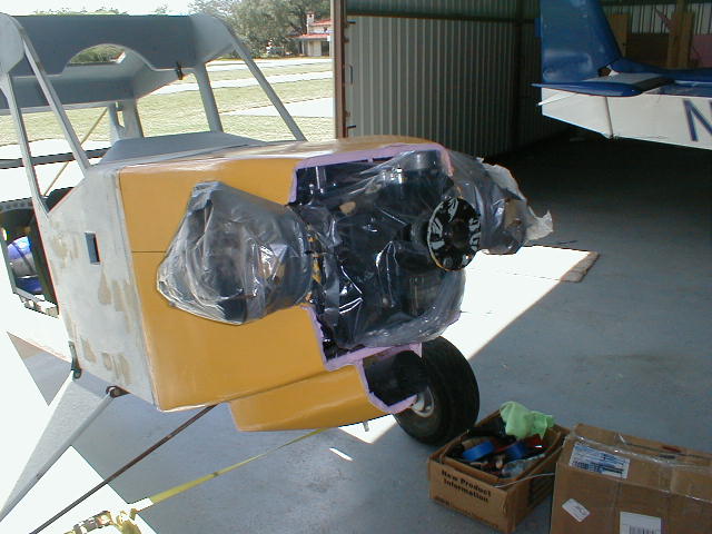
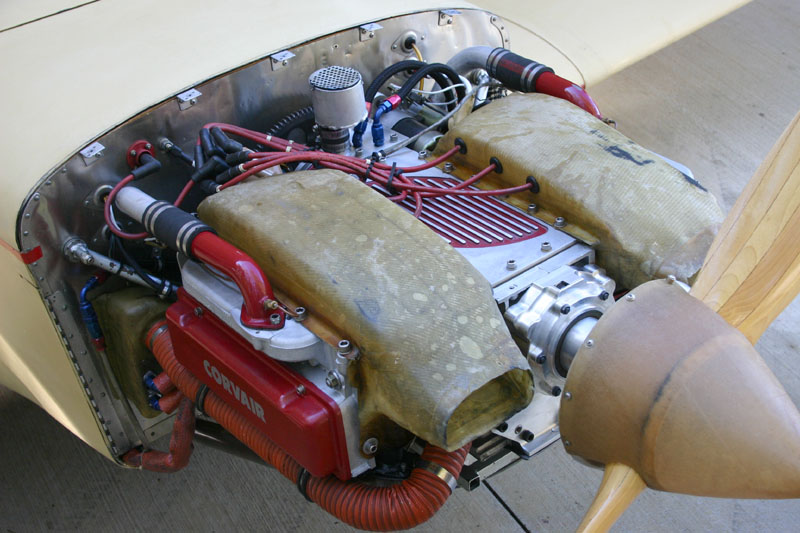
 Here's a rough setup, but I could see right away that (1) I need to go wider with it or I'll have to fit the sides of the cowling around a whole bunch of parts of the engine besides just the valve covers, and (2) that carb sure hangs down low! I guess I'll just need to start fitting and eyeballing and see where and how best to shape it. I plan to use internal cooling plenums on the cylinders rather than full baffles inside the cowling, like Mark Langford's:
(Oct. 4, 2009: starting the construction of the new cowling)
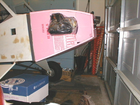
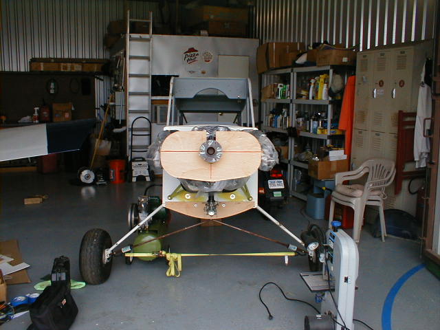 I started the buildup with an idea of what I wanted the new cowl to look like and I cut a flat nosepiece and bottom cowling lip out of thin plyboard to mount "hard" in place to build up everything in between.
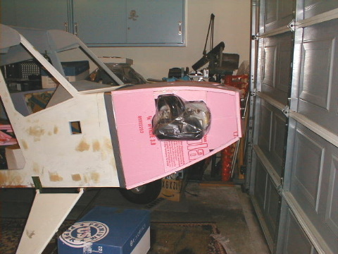
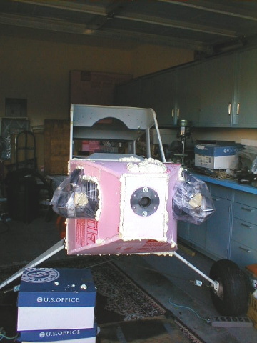
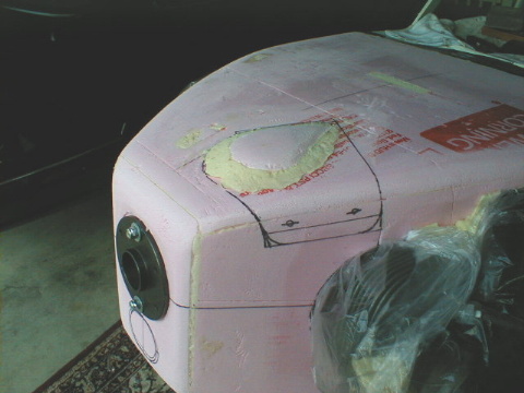
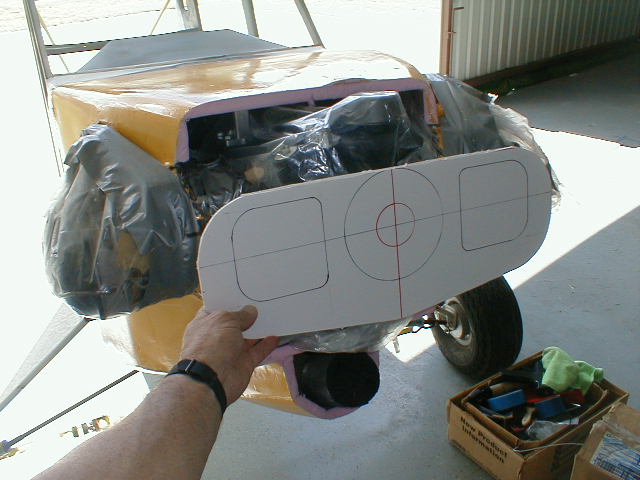
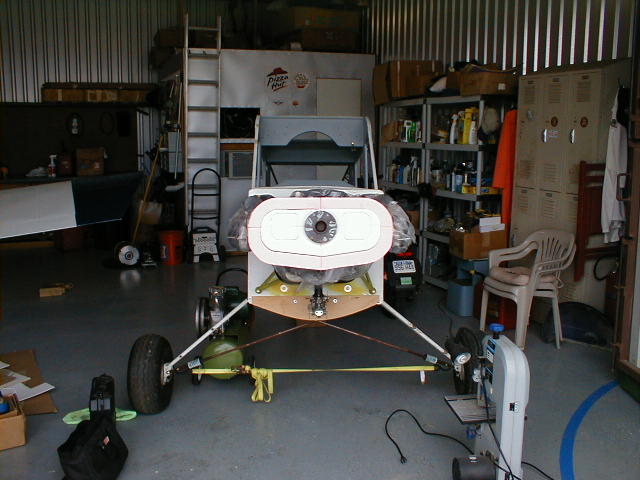 Next step was to hot-glue two layers of foam board onto the plyboard nosepiece and add my drawing of where the air inlets might go. This gives me an idea of what I need to adjust, and I could see right away that the inlets need to move outboard by about 1" to give the cooling plenums a straight shot into the cylinder fins. Easy enough, and it will actually improve the BirdDogginess of the look if I spread the cooling inlets farther apart.
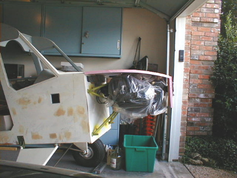
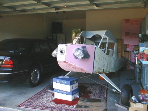
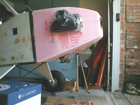
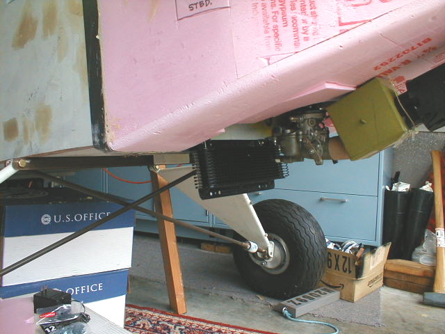
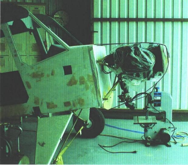
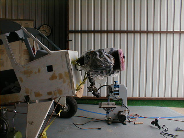 Side view shows that I'll be able to enclose the carb just fine (disregard the flexible gooseneck lamp on the bandsaw in the background), but I'll have a few things sticking from the top of the cowling. No big deal.
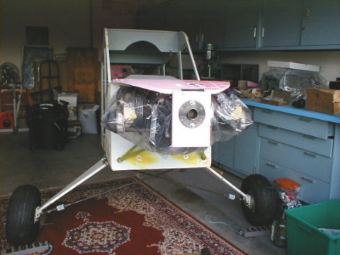
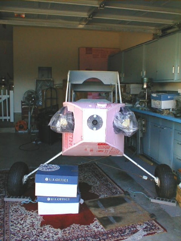
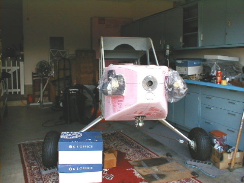
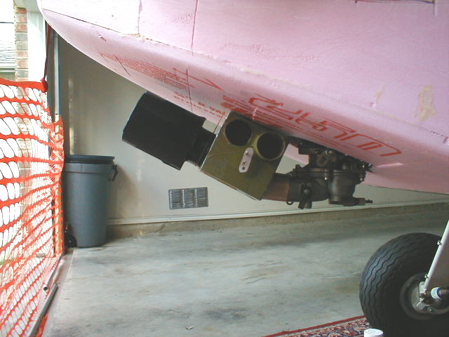
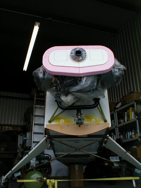 Front view from below shows that I'll have most, if not all of the valve covers sticking out the sides of the cowling. Again, no big deal and definitely a plus for cooling.
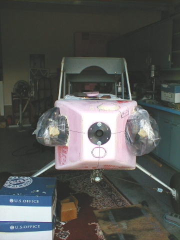
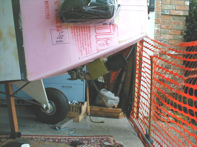
 Drawing in the lines of where the cowling top and bottom might go, it's starting to look like it might work! It will definitely require notching of the nosebowl and sides where the front two exhaust return bends go though.
So, if you're not building yet.......why not??
Return to My M-19 Project