M-19 Controls
M-19 Control Systems
Reorganized January 13, 2008
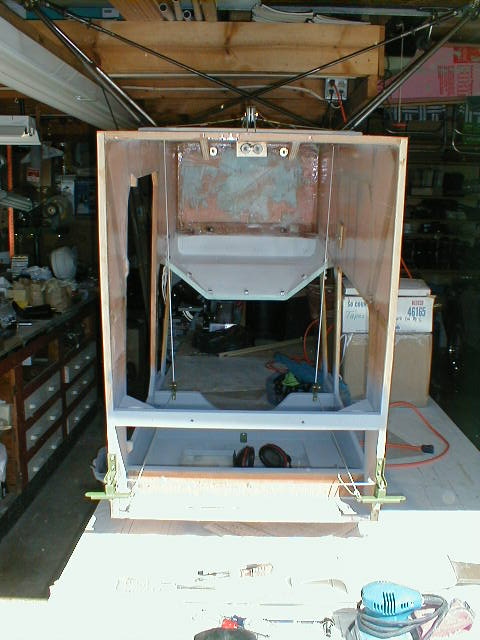
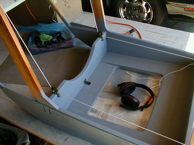
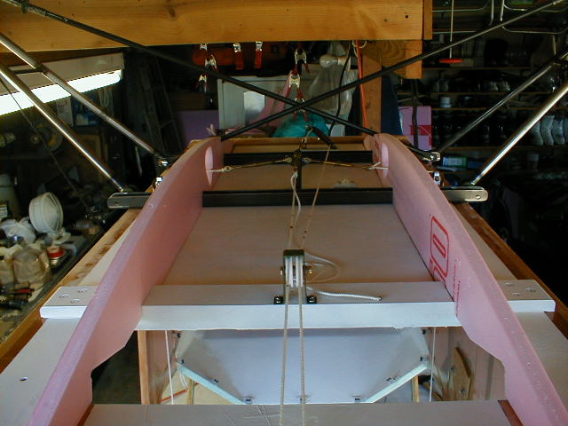
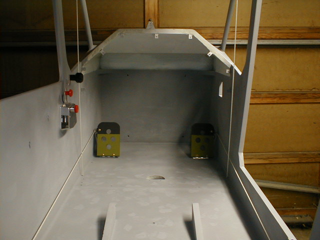
Here is a view of the airplane cabin on its back, with the landing gear temporarily attached to the brackets. Pay no attention to the hardware; it's all temporary. As you can see, I'm running out of space! The garage door opener hits the gear leg, so things have to move. Also visible are the inside of the top cowl (white primer), instrument panel mounting clips, and white cord temporarily installed as "control cable" to verify routing and proper clearances for everything.
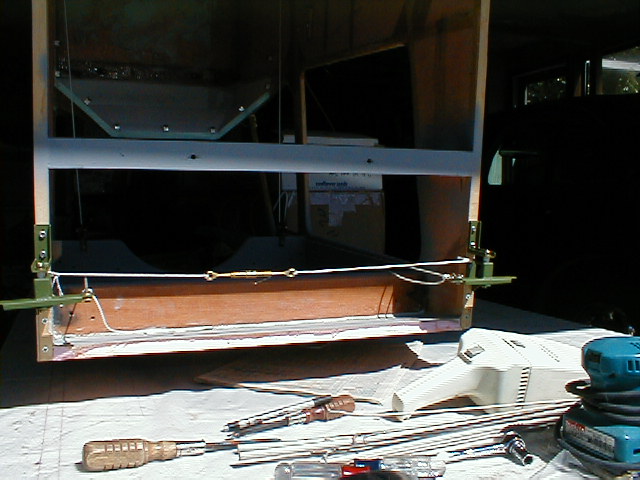 Here is a closer view of the aileron bellcranks. I have since installed control stops at the bellcranks to limit aileron travel, rather than the control limit plate Marvin used on the prototype.
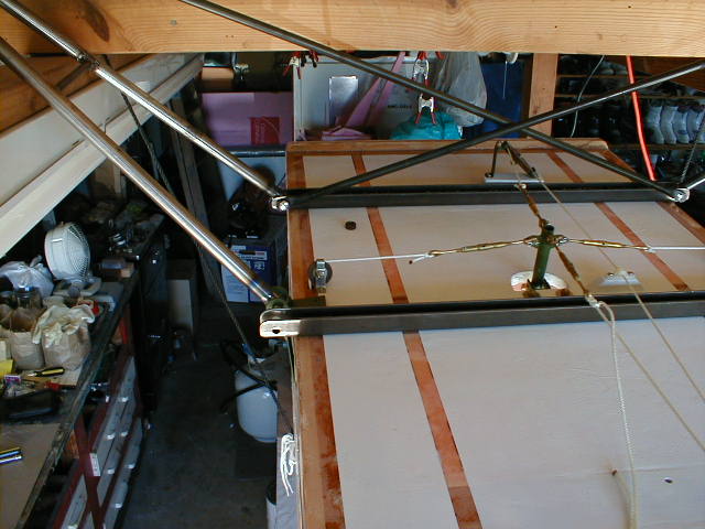
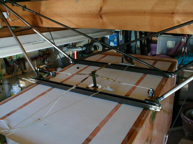 Here's a view of the control stick and cable setup, again with cord temporarily run in place of control cable. I don't like the turnbuckles here (at the stick), and will move them into the cabin for better access. There will still be an access panel in the belly for access to the control stick. Note my reversing pulley setup for the elevator control cables; took a bit of tweaking and messing around to work out all the cable geometry. I've primed the bottom of the cabin floor with flat white, and have masked off where the belly ribs and panels will get glued onto the cabin. The inside of the belly will be flat white, to help with inspecting inside there.
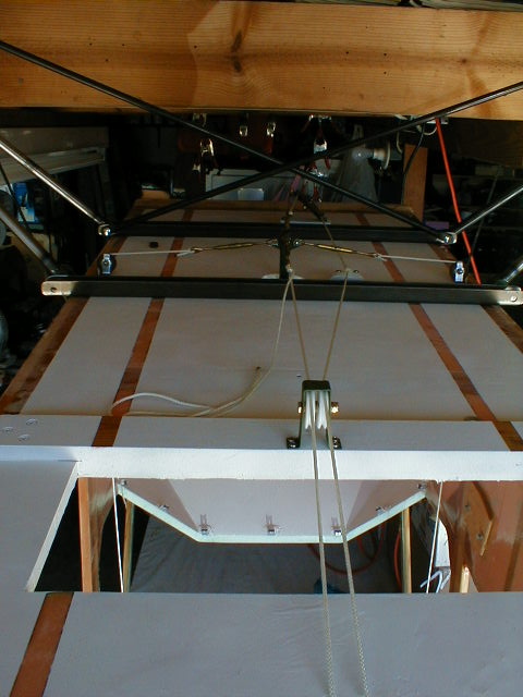 Here's a closer shot of the stick and cables, from another angle. I had to install a fairlead for the elevator cable coming back from the reversing pulley, to get things to clear. However, as you can see from this angle, I've got to move the fairlead and mounting block because the angle that the cable leaves the pulley is too radical. The double pulleys are the "idlers" required to offset the cables under the bottom of the seat (I lowered my seat, which required that I cut a hole in the cabin floor, which required that I add the seat support brace running across the bottom, which required that I add pulleys, which... oh well, you get the idea)!!
 Another shot.
 This is a shot of the control stick stub and universal. I made my control stick removable from the pivoted stub, to allow tilting my seat forward and for easier access to the cabin area when doing installation or maintenance. The two pieces are joined with a clevis pin. The mic cable runs down inside the stick, and will have a quick-connect for when I remove the stick. Also visible here is the backing/mounting plate for the throttle quadrant, as well as the aileron cable running up the inside of the cabin. This is where I'll install the turnbuckles, to allow easy access from inside the cabin. Just think- you can build your airplane faster and have less headaches if you DON'T do all this stuff I've done! "Just build to the plans"!
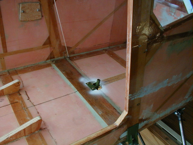
 Here is a shot inside the cabin roof. Everything that has grey primer on it has been sanded, filled, sanded, filled, smoothed, primed, sanded... and I hope never sanded and filled again. Still lots to do.
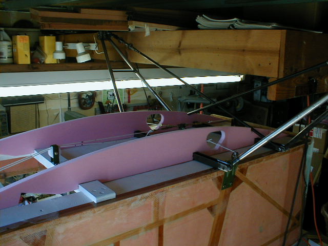 Here is a shot with the belly ribs temporarily installed. Note the cutout holes for the aileron cables to pass through. I made mine rather large, to allow getting at things through there besides just allowing the cables to clear. Also visible is the double idler pulley for the elevator cables to clear the bottom of the seat (seat is not installed in this photo), and the notches in the belly ribs for the spring struts. Not sure how I will smooth and fair the holes in the belly where the spring struts emerge.
 Here's another shot showing the belly ribs temporarily in place.
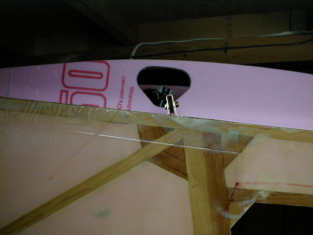 Here is a view of one of the lower aileron cable pulleys (not in its final exact location, just sitting there). You can sort of see how the cable is then routed from the stick up through a hole in the floor to the upper pulleys at the main through-spar.
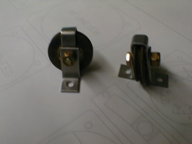 Trying out the macro mode on the new digital camera. Forgot to wait while it autofocused, but you get the idea. My lower aileron pulleys; Jeff used stainless to make the brackets out of.
 Close-up of the control stick, showing the parts and pieces. Upper and lower parts separate with a clevis pin holding them together right above the floor line, allowing removal of the stick for working on things. Mic cable is fed down through the handle and exits through a hole in the lower part, with a connector in between.
 Here's what the inside is looking like at the end of October 2000, with rudder pedals temporarily installed so I could check cable routings and angles. It's white twine, not real cable. Also installed twine at the aileron cable routings, again so I could check clearances and routings. I was concerned about the starboard rudder cable clearing the opening for the cabin door, but it clears nicely. Visible on the starboard side is the cabin air door opening. Pay no attention to the pockmarks and rash all over the floor; those are where I've had to fill and sand rough spots, and they will disappear once I do final sanding and priming.
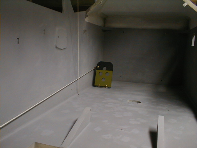 A closer look at the rudder cable routing as it passes the aileron cable. Plenty of clearance. I used fairleads to guide the rudder cables down the fuselage, rather than continuous nylon tube as the prototype uses. Also a good view of the "filling rash" ;o)
 A closer look at the area where the throttle quadrant is located. I ran some white twine where the throttle and carb heat cables will be run, which pointed out some potential conflicts unless I route the quadrant cabling tighter to the cabin wall. No problem, but it's better to find this out now than later.
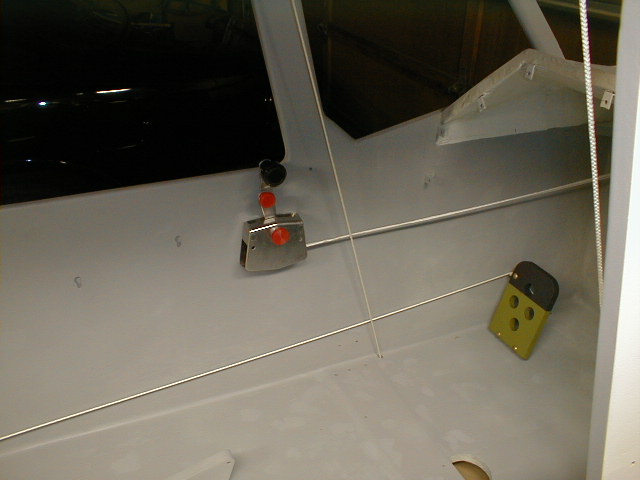
 This is my tailhook release. With a single-place airplane and no electrics, most flights will be made with no one around to help me prop it, so I'm installing a tail tie-down hook (like used in glider tow) for holding the tail while I prop it. I installed my cabin door on the starboard side and all engine controls on port side, meaning I need a reach-in sliding window on the port side so I can control the engine while starting it (from behind the prop). I'll then have to walk around the (running) engine/prop to get in... and I don't trust chocks with the plump mini-tundra tires. All of this so I could have stick in right hand and throttle in left! Anyway, with a release in the cabin, there should be less fiddling around with trying to pull chocks after climbing in (although I will use both chocks and the tie-down, I'll pull the chocks after the engine is running but before climbing in). The release cable, obviously, has not been installed in this photo; I used a piece of wire to line up the cable adjuster center with the lever arc.
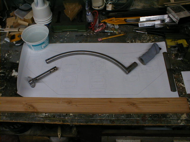
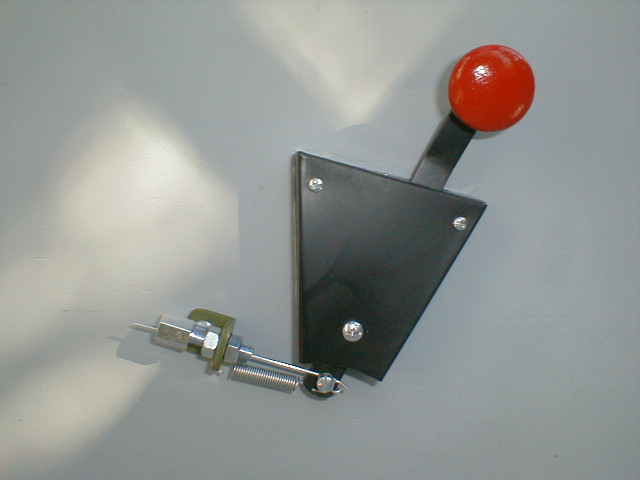
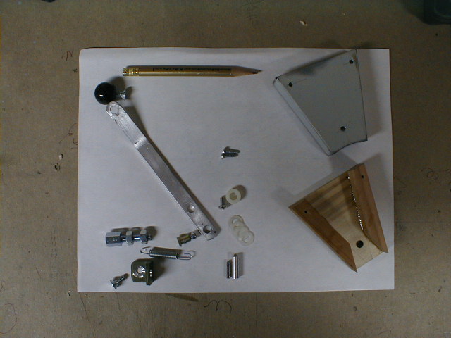 Here's the exploded view of the tailhook release lever. Just a bunch of pieces made from "table scraps". This view shows a small black hardware store knob, while the previous photo shows a wooden drawer pull, painted red. Not sure which one I'll end up using.
If you're not building yet,.........................why not?
Return to My Flying Squirrel Home Page